24/7 automatic measurement of equipment grounding resistance with instant alarms and full history, so ESD protection actually works on the line.
Machines in electronics manufacturing and precision production lines build up static charge through friction and material properties. If equipment is not properly grounded, that charge can disturb processes and skew test data — and worse, damage components, lower yield and reduce capacity. Equipment is therefore designed with an electrostatic discharge path to ground, and continuously monitoring the resistance of that path is the key indicator of proper grounding.
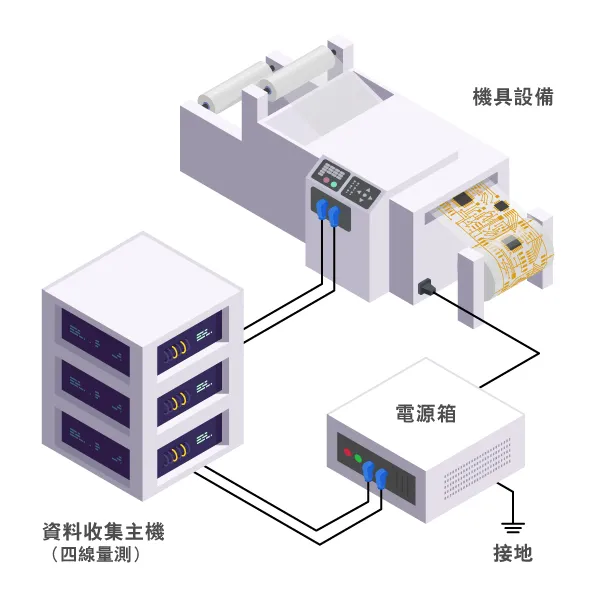
Our ESDR Measurement System detects grounding status in real time, measures automatically, checks each reading against its limit, alerts immediately on any abnormality and keeps complete records for traceability. For lines that need ESD protection, it cuts manual inspection work and makes sure protection is really in place.
Automated measurement
Periodic, standardised measurement cycles covering 0.005 Ω to 20 Ω micro-resistance, reducing manual patrols.
Real-time alarms
Live readings with alarm outputs on abnormal values to improve line stability and uptime.
Self-calibration
Built-in precision reference resistors support self-calibration and external verification, lowering maintenance cost while keeping accuracy.
Snapshot reports
Store and review up to 1 million records for history tracking and failure-mode analysis.

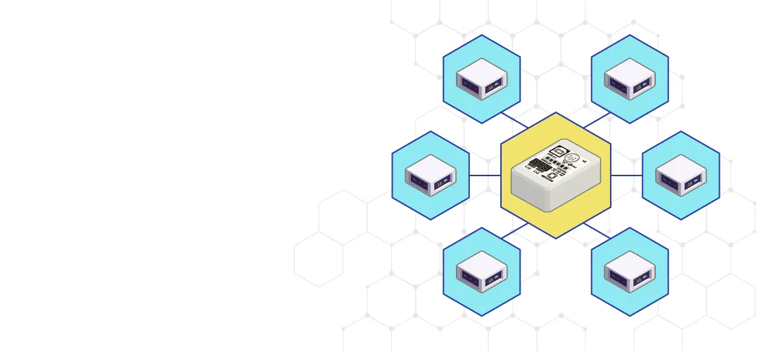
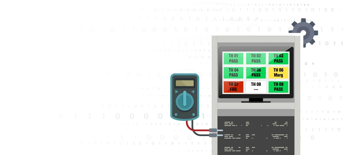
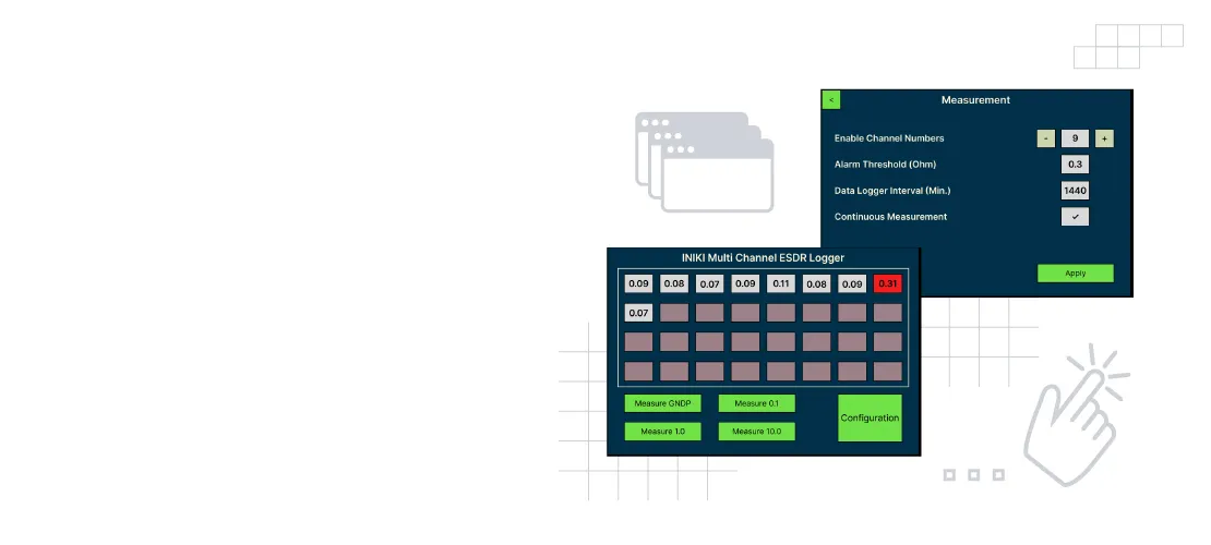


Typical resistance limits by application
| Limit | Application / equipment location | Common references | Purpose |
|---|---|---|---|
| < 0.1 Ω | Process fixtures to ground (plating fixtures, RF chambers), electrostatic chuck conductive layers | SEMI E176, micro-ohmmeter practice (Hioki, Chroma) | Stable conduction at high frequency / high current; avoids process non-uniformity or faults from resistance drift |
| < 1 Ω | Touchable metal enclosures, flip arms, robot arms, ESD ground wires | ANSI/ESD S6.1, SEMI S2, IEC 61010 | Operator safety and a reliable discharge path; prevents floating grounds and ESD events |
| < 5 Ω | Sliding carbon brushes, spring contacts, conveyor end points | Equipment acceptance criteria, internal continuity guidelines | Reliable conduction while keeping mechanical flexibility for rotating or intermittent contacts |
| < 10 Ω | Non-critical ground points: machine sockets, general frames, ESD workstation test points | ANSI/ESD S6.1 (maximum), IPC-A-610 recommendation | Most tolerant limit for non-critical points; avoid for high-speed or sensitive areas |
Installation process
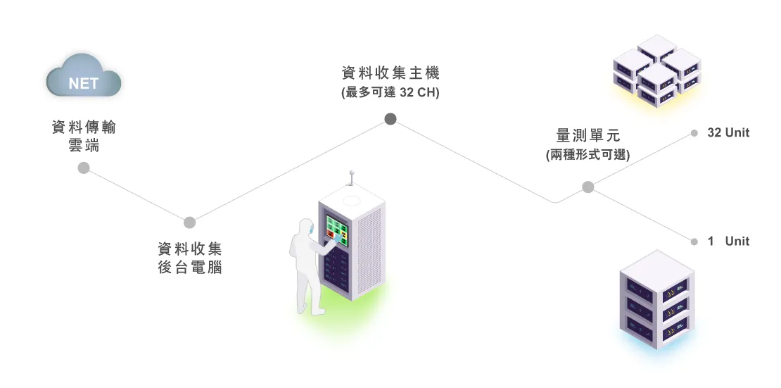
- Identify measurement points on the machine
- Install the measurement system
- 24/7 automated measurement
- Instant alarms on degradation
- Annual in-line calibration
Specifications
| Item | Specification |
|---|---|
| Channels | 32 channels standard (expandable) |
| Measurement method | 4-wire Kelvin connection, one-key automatic measurement |
| Ranges & resolution | 0.1 Ω, 1 Ω, 5 Ω, 10 Ω; resolution down to 0.001 Ω |
| Self-calibration | Three built-in reference resistors (0.1 Ω / 1 Ω / 10 Ω), 0.1% accuracy, automatic calibration |
| Logger | Configurable interval (every 5 seconds to once a day), 3+ months of history |
| Fault & alarm records | Logs abnormal channels and times for alarm root-cause review |
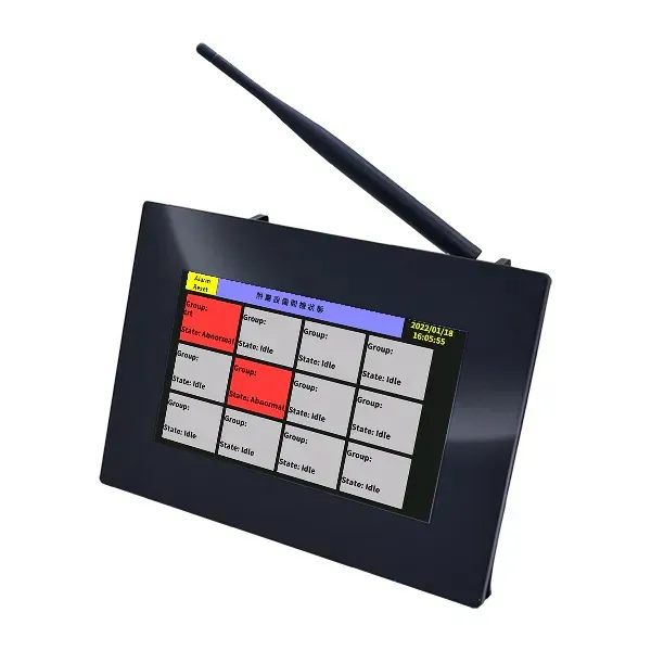
| Interface | 5" LCD touchscreen, Chinese / English UI |
| Data export | CSV export, USB download, remote query |
| Communication | USB (CDC/HID), RJ45 (Modbus TCP, optional), RS485 (Modbus RTU, optional) |
| Calibration test points | External precision instruments supported; 0.1 Ω / 1 Ω / 10 Ω test points provided |
| Storage | At least 3 months of data (depends on logging interval) |
| Power supply | DC 12 V – 24 V |